Yellow Jacket Hovercraft - Kirk's Story
My latest project, (the one that distracted me from the Yellow Jacket...)
My first discovery of the Yellow Jacket design
In 1991, while searching for that "just right" hovercraft design I was
destined to build, I discovered the Yellow Jacket on microfilm in
a (Popular Mechanics Magazine article) in the
Corvallis, Oregon public library. Unfortunately, the year,
month etc., of the magazine issue was not included on the incomplete article
image. I had to live off the low quality, microfilm print for some time.
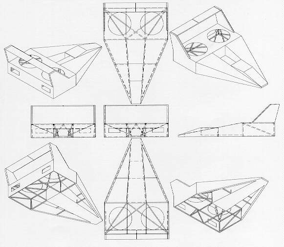
Here's a Yellow Jacket "like" Frame
design I started based on the glimpses of the Yellow Jacket I had
from the microfilm library article. I was brain storming... that
attitude adjustments and mild banking might be possible with the horizontal
stabilizer/aileron like wing at higher speeds. Also, shooting to be more
aerodynamically more stable than that of a round nosed craft
(less prone to an aerodynamic stall). -other problems reside... I began to
understand why most recreational hovercraft take the shape and form which
they commonly do.
My 1992 trip to see the original "Yellow Jacket"
featured in the article for the first time.
I called Popular Mechanics and talked to the fellow who wrote the artical on the Yellow
Jacket, and from him I found the name of the designer and that he was a helicopter designer
who at least used to work for Sikorsky. They managed to give me his current wherebouts, and
I went for a trip to talk with him. On arrival, I took videotape, measurements & talked
design/performance improvement ideas. I brought prints of 2D and 3D images to express my concepts.
Yellow Jacket was a shocking, rusting, rotting mess with the engines stolen
and the paint a peelin. Below is picture of the Yellow Jacket which
I took on that trip. Eugene said
it had been parked for 13 years (at that time).
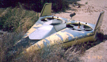
Whew, so much for taking a ride.
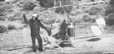
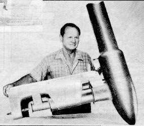
Eugene had other interesting projects going on, including a helicopter kit.
He also designed and sold propane jet engines as kits or assembled.
Collecting statistics/Specifications for design
alterations to build my own.
i.e.. prop pitch, foil, sizes, weights, etc.,.
I'm linking this part of the story to my
"statistics/Specifications" information because you probably don't
want to sift it out of my story telling style. But I thought I'd note
that the airfoil appeared incredibly complex when I first observed it in
person during this 1994 trip. Knowing that a helicopter designer put
this thing together, I felt very small in the way of knowledge. I
hesitated, then asked naively "why does the trailing edge swoop sharply
upward over the rear 1/3rd of the foil?". He laughed..., so I laughed as
though I knew why. He then replied "Because it's so badly warped!.
In Eugene's words "It's supposed to be a standard Clark Y airfoil".
Some of my designs considered, BASED on the Yellow Jacket
design:
Composites, wood, aluminum, steel, sheet, combo's of all
the above.
*Steel frame design (29kb)
Notes: Modeled with a 25hp marine engine.
*Foam and composite Hull design (45kb)
Really starting my hovercraft build:
During a business trip to San Diego, I drove up to Eugene's place
with a friend to take some last minute measurements from the hovercraft, prior to starting
my own. I thought to myself "Why not make an offer on the old hull?". I did, we
haggled, we laughed, I bought it.
How in the world am I going to get this thing
home? -to Corvallis Oregon!:
Now I'm frantically trying to find a friend in San Diego who will keep the
hull for me until I can make it back to pick it up. But then, I thought
perhaps I could ship it North. I called around and got quotes
from $400 to $500. Wow! I had never shipped anything like
this before. Finally I spoke with Reddaway, who's nearest shipping dock
was in Fontana, closer to L.A. than Hesperia, where I'd picked up the
hull. They indicated the other quotes were probably considering
crating up. Reddaway said they could "Top Load" it, therefore not
requiring crating. Below is a photo of the Yellow Jacket on it's side
in the truck (at about 10pm) as we began to unload it at Reddaway's
Fontana shipping dock in March 1994.

When my friend and I unloaded the hovercraft onto their shipping dock
however, they became incredibly nervous, afraid that I may accuse them
of the damaged appearance of the Yellow Jacket. I reassured them I
wouldn't and reluctantly, they took Polaroid's and shipped it to
Albany, Oregon for me charging only $120.
Thank you Reddaway!
Home at last!:
Images of the Yellow Jacket, tired & worn, but IN MY GARAGE!
Show's what a mess it was during disassembly.

The photo above shows the skirt, falling apart from age and more than
likely an overdose of fun over the years. Notice the steel bar sewn into
the bottom of the skirt. More on this later.

Can you say... RUST! This photo illustrates the condition of the frame in
some portions where foam was previously used in the hull for water
flotation. It has trapped water and contributed to the corrosion. The
rusty parts on the floor were dangling from the aluminum skin edge, also quite corroded.
I'm sure electrolysis (contact between dissimilar metals) is partly to blame
too. Digging out the foam was NOT a fun job. I'll be sure to find a
better way to do this.
This is the prop shaft removed, with Torrington needle bearings seized
to the shaft due to corrosion.

Making that list of "Oh, I never thought of that" stuff, to ask Eugene:
Composed a 12 page letter & mailed it off.
Eugene's daughter received my letter and called me --
Eugene had passed on three months after I obtained the hull. An incredible loss
of many things. Though I'm proud to share the Yellow Jacket dream.
Information about EMG Engineering products like Jet
Engines, Kit helicopter, etc. are now available through
Robert Q. Riley's
website
Progress in Strip Down & Rebuild
A June 1995 rear view, with the
puff ports and back wall removed. Taken right after I
sandblasted the hull & frame.
A June 1995 image with some annotation of
work to be done at that time.
Deciding go with a closed canopy means work...
I have built a fiberglass cowl that encloses the pilot and engine.
Check out these pic's.
THE CANOPY:
Let me start by saying I'm no pro with this kind of stuff. I believe you can learn the most
by asking around, until you feel comfortable taking it on. When you're ready to do any
fiber glass work, hopefully in asking around you found someone who buys
resin and fabric bulk, so you don't pay a ridiculous price for it. The things I have done as
described below, was on my own, but not without being coached from friends who have
been there. For the mold and two bodies described below, I used 2 gallons of resin and
about 40-50 square feet of mat and cloth.
I know you may have already seen this, but just in case, check out
the image of the
electric car body compared to my hovercraft body .
The body on the car has a positive draft and is quite simple as
compared to the contours of the one I ended up with. The body on the
car is made of ABS plastic. Not good after much sun (w/out paint),
not good considering the vibrations and stress a hovercraft may dish out
and not good for heat as it is a low temp thermoplastic. The Canopy
bubble itself is identical. The unmodified ABS parts are made by :
Mark Murphy at Blue Sky Design. This link will
get you to his Phone, mailing address, etc.
Assuming you have seen those two pages, here is an over view:
The overall plan was to modify the simple ABS body to mate smoothly
to the Yellow Jacket's surface while maintaining the upper contour
(as is) to mate with the incredibly cool looking bubble.
Then, to make a fiberglass mold off the ABS "plug" so I could produce
a stronger, more robust body, i.e.: heat, vibration, UV. Not to mention
the fact that I can pop out more body's from the mold if needed. And
I did need to...
A more detailed explanation:
I bought an ABS body (top shell only) from Mark, cut it 's base off.
About 14" from the bottom of nose, upward. Tapering to 0"(cut)
in the rear, because the pilot's cockpit is sunk into the hull of my
craft. The rear is intended to cowl the cooling air which flows
over the air-cooled engine, so heat resistance and proper clearance
(why rear is raised more than the front) is important. I then took the rear
base of the body (which is over the fans) and used duct tape to
hold the left and right sides in together (about 7" wide at the
narrowest spot). This is significantly narrower than the normal
width of the ABS body (approx. 24 inches). Next, a bit of crude trimming
to get a reasonable fit to the (far form imperfect or symmetrical) surface
of the Yellow Jacket. Once it generally looks good, the next step I
took was to begin the blend to smoothly transition the ABS body to
the aluminum hull. I wanted to add some tapering blends ranging from
none (in the duct area) to ~ 2" and larger radii, most
obvious just in front of the ducts and all the way forward to the
nose and back to the duct on the other side. This was done with spray
foam, then hand carved. I started this by laying a $2.00 sheet of thin
mylar across the YJ hull and then laying the body on top of it.
This way the foam will settle to the contour of the YJ (but not stick!) while it cures
against the ABS body too . Next, I used strips of 2" dry wall repair tape
(like a net w/ 1/8" spacing) to create a sunken) blend in the really big gaps that
would otherwise be filled inches deep of foam. This tape supported the foam
well when sprayed over it. Next I sprayed
polyurethane foam (from a can) to roughly add enough material all
around the edges to later carve the desired blends from. The first
surprise was how much foam it took. I used about 7 cans, (~40.00) and I thought
this was a fairly small job, only running a perimeter of about 16 feet.
The next surprise was discovering the foam that comes in a can, does not have a
catalyst (or it would cure in the can) so it more or less air dries.
Which means the thick spots (greater than 1.5") took longer to cure and was
more dense, making it a challenge to carve. I'd recommend adding
tape, wood or anything to fill areas requiring foam, keeping the
foam layer to 3/4" or less where possible. This is also assuming
were talking about a plug for mold purposes, not a functional body.
I don't know how you could do the job with a 2-part (catalyst type)
foam and still direct the foam into a crevasse where you want your
blends, but I'd give it consideration if I had to do it again.
On to the next step, carving. I found the best way to do the first pass,
rough blends was to use a drill (I used an air drill).

I used different radii of wire wheels in the chuck. They rip through the
foam like it was dust, conveniently in radius's. It raises a lot of it
into the air too. Once close (but over sized) I used a body working
tool called ?. It is common, 2-3 inches wide and about 20" long. and
flat. It LOOKS some what like a hand plainer that is normally used on wood.
It worked very well for most of the blends I needed. Always keep moving you sanding
tool in random directions. Much of the
inside (bowl like) blends however, were carved with sand paper
wrapped around similar shapes I could find laying around the garage.
If you haven't done any sculpting or body work, the time it takes is a
function of your learning curve, multiplied by 10. I believe one can get educated on
this, but the rest is art. I needed to reapply more foam where
I goofed and to fill some thumbnail sized bubble holes here and there but
at this point didn't worry about anything smaller. Watch out, the
density of the new foam is usually a bit different than
the foam in the previous layer. Don't worry too much about
feathering the foam into the ABS either.
After the foam job is roughly the way I wanted the final pass to be
(or slightly smaller). I Began the Bondo (body filler) work. This was the
surface which was to be near perfect in general shape(opinion).
I applied it with a typical,
cheap plastic Bondo applicator. If you haven't used Bondo before,
don't worry. Read the directions and mix it well prior to starting
each batch. Oh, and if your job is compatible to mine, buy 1 gallon.
I applied it just thick enough to cover the foam leaving a 1/16th to
1/8th typical thickness. Of course some gaps and bubbles required
more. I sanded, using 40 grit and contour appropriate tools. More
Bondo on the shallow spots, sand, apply, sand, apply, sand...
You get the idea. As the large dips and woweee's became satisfactory, I
moved to finer sand paper until I got to surface scratches of 80 grit
only. (No 40 grit scratches).
Once it was perfect (the definition evolved as I burned out),
I was ready to spray on the primer and fill those 80 grit scratches.
I carefully moved the mold plug/body as not to crack it, (but did anyway) to a blocked
up position for final primer and mold lay-up.
I used polyurethane primer first because other paints may attack the ABS. But
don't use it out of a rattle can. Out of the spray can polyurethane
paint never seems to cure, again no catalyst in this type. Spray it
from a cheap paint gun if you have to, you'll be sanding in anyway.
In my case, I sprayed it with 3 thick coats. Let it cure well, then
found it quite nice to sand. It filled all the 80 grit scratch marks
well and even many of those 40 grit scratches I missed. 2 more coats
and a light scuff and I was ready to squirt it with polyester primer.
The idea of the polyester primer was to protect from out-gassing that
might occur during the lay-up. Again, a light sanding with 120 grit, and
it was ready for the next step, waxing.
The wax had the consistency of bar soap. Rubbing it in shined up the
surface and even filled some oversights nicely. Much like polishing
a car.
Next, was spraying on the mold release. A water soluble, alcohol
based solution which looks just like Palm Olive liquid dish washing
soap. I learned the hard way that you must dust on the first coat, or
it does some strange ugly things. I had to wash it off with a sponge
and water exclaiming words I'd rather not write. After dusting on
the first coat however, and the second and the third... the fourth
thin coat left me an appealing outer surface which was to become the
inner surface of my mold.
I brushed on the inner surface of the mold, the gel coat. It was
recommended to me to do a gel coat surface because otherwise, the resin
shrink that occurs is will reveal the cloth pattern in the surface
contour. A gel coat (just resin with pigment -no cloth or fiber)
only surface is allowed to mostly cure prior to adding the first
layer of cloth or mat. Next I used 2 layers of random mat to make
the mold surface laid up on the entire surface (one at a time). I
did it in manageable resin batch sizes, mixed to cure in approx. 20
minutes, I was able to thoroughly soak the mat with resin for an area
of about 4 square feet before the resin began to cure. Be patient.
Ask your body shop dealer for a couple of
tools appropriate for your job. I don't know what they're called but
they are aluminum rollers of different diameters with small ridges
and are used for working the resin into the fabric and the air
bubbles out. If you have more time than money, a paint brush or
two will do (appropriate sizes for your job). Using only brushes in
other jobs, I found it best to slop the resin where you want it, then
poke and dab to work out the bubbles. It works, it's just a bit
slower.
After the surface was covered with 2 layers cured, it was time to add
some wood. Not for structure, the mold was pretty stout with the 2
layers. So why the wood then?, By curving the bases of the ABS body in for the fan duct
radii, I created negative draft angles, so the part eventually
made by this mold I was making would not just pull out of the open
end. I planned to split the mold down a centerline front to rear,
allowing a mold half on the left and right sides to exit outward off
a potential plug and parts. This meant the mold needed a mating face on the
centerline in which to bolt together. I added enough random mat
strips to build up some flat surfaces along the centerline to be
split (parting line) and laid pieces of ~12"x 2"x 2" wood along each
flat spot, wrapping mat sheets up the sides from the mold surface to
permanently adhere them to the mold. Once that was done, I drilled
holes through them so that after being cut on the parting line (later)
they would have a bolt pattern to align and clamp them together as
one. Next I used an electric grinder with a flexible grinding disk
to trim the excess fiberglass and resin which dripped off the base
while I was doing the lay-up. Then, finally, I used an orbital saw
(only to get the depth required) to cut the wood, mold and yes, that
plug I spent hours on, down the parting line. For most cases a skill
saw would be better and more likely to produce a straight line.
Excited, edges trimmed and parting line cut, I squirted a garden hose
between the exposed edges of the left mold and plug. In minuets, the
water had dissolved the mold release and was forcing it's way
between the mold and plug. With a bit of persuasion, the plug fell
out of the mold half. The other side went the same. The plug
ejected, I put the mold halves together with the bolts in the holes
previously drilled and I had a parting line that was roughly 0" to
1/16" in the worst case. Success!
Whew!, That was a couple of weeks worth of evenings. And still no part.
I wanted the body to be light, so after viewing other similar light
structures, such as canoes, I thought I had the solution. I used a
strip of scotch tape to prevent the parting line from filling with
resin during the body lay-up. Then, after waxing the mold and
spraying it with mold release as was done for the plug/mold lay-up
described above, I put on the gel coat
and one layer of 3oz cloth against the mold. Then for structure, I
laid strips of 1/4" x 1/4" foam tape running top to bottom spaced about
every 12". I laid a strip of random mat (thicker than cloth) about 2"
wide and as long as the foam tape, over the foam tape to produce an
air filled tube shape. This worked great!

My part weighed less than
5 pounds. It was questionable however if it was strong enough to
take the vibrations. It took me the better part of a week end to do the part lay-up.
About one week later, the difference in
thickness' of the walls due to the structural tubes I added, caused
uneven shrinkage to occur and added undesirable ripples in the
thin walled sections between them. Yes I was depressed, but glad I had a mold :-)
I made another body, using a single layer of mat, which provided
ridged walls, will require minimal structural additions and still
only weighs less than10 lb. (Shell only). It will require some structural
walls inside, but they will double as cooling air ducting for the
engine and a separation wall between the engine compartment and the
driver.
I added wood blocks into the fiberglass body at points where it is to
be mounted to the YJ hull. This allows the stress to be
distributed more equally over the body piece.
That's it for now on the body and canopy.
Forging ahead, more progress...
This is a picture from September, 95, showing
the assembled fans in place. I have started the engine and tacked it up
a bit. Still need to rebuild the rear wall, puff ports, belt tensioners
and put the skirt on to be ready for a hover test. Well, maybe not the skirt...
In addition, a great deal of cosmetic work lies ahead before a practical
hovercraft ride is possible.
Starting up the Yellow Jacket for the first time in decades?
At least 15 years, was an exciting moment...
A new engine where there once was two, new enclosure, drive system
and fans too. I think it's more like a mutant than a rebirth. At this
moment I could relate to Dr. Frankenstein. The clutches smoothly engage at
2000 rpm. At an idle, the props remain at a stop. The "V" belt's
90 degree twist
from the horizontal drive axis (v belt go-kart clutches) to the vertical prop
shafts seem to handle low prop rpm's just fine (this was pushing the rules
according to the book with my center to center distances and pulley
diameters). The backside belt tensioners seem to bounce a bit due
to the 2 stroke engines rough idle,
but smooth out after gaining a little speed. With the prop rpm of
aprox. 1000, the carpet, loose rags, etc., are blowing out into
my driveway, I decided this is not the place to test higher rpm's.
Been side tracked for too long, getting back to the Yellow
Jacket project...
Side tracked by (fun) Electrathon activity
I've decided to try and get hovering by the July 97 West Coast
Hover-Inn. At the end of April (97) I summarized what was left to do:
- Determine and build maneuvering method: Puff ports, deflection vanes or
just leaning.
- Wiring: kill switch('s), gauges, etc. -Done 5/97
- Fab rear wall: currently open where puff ports once existed.
-temp wall done 5/97
- Engine: already mounted and operational, needs adequate cooling airflow
duct work.
- Cowl completion: Structural support where needed, design & build.
- Canopy attach and opening method.
- Interior: Design & mount seat, carpet?, gauges, etc.
- Fuel Tank: Mount & plumb w/filter and accessible shut off valve, vent
to air filter intake, accessible filling. -Done 5/97
- Cosmetics: Body work, paint, trim? etc.
- 5/97 added tuned exhaust pipe to this list. Faxing Dyno-Port.
- Fab & mount skirt
- Land surface testing & tuning
- Design, add & test floatation method.
May 97 progress report: Hover ready?...
 I bought one of those aluminum tanks you see in the dune buggy or hot
rod magazines. Very light and simple to mount. Done! I bought one of those aluminum tanks you see in the dune buggy or hot
rod magazines. Very light and simple to mount. Done!
 Carb is all that hangs out. Cable and fuel
have since been routed internally. Carb is all that hangs out. Cable and fuel
have since been routed internally.
 Minimal clearance required for exhaust. Minimal clearance required for exhaust.
Ignition switches are wired and I've built a temporary rear wall which
completes the hull seal with exception to a skirt. Next, I'll attempt
a skirtless hover to confirm that my neutral C.G. is where I want it to be. I'll post
pictures here. -Need tuned pipe first.
PS Current all-up-weight (with out canopy) is currently 218 lb
with 1/2 a tank of fuel on board. The canopy and mounting hardware
is expected to weigh approx. 20 lbs.
 Engine off, I'm sitting in the position which,
if I planned my center of gravity correctly, I will be at a neutral or
slightly reversed hover. Engine off, I'm sitting in the position which,
if I planned my center of gravity correctly, I will be at a neutral or
slightly reversed hover.
 1st run up test. I'm thinking to myself WOW!
those fans seem to be moving fast and that I should NOT have a hat on.
The hull is sitting on it's wheels, not hovering. Test proved I need
a tuned pipe and perhaps less pitch. I'll try the tuned pipe first... 1st run up test. I'm thinking to myself WOW!
those fans seem to be moving fast and that I should NOT have a hat on.
The hull is sitting on it's wheels, not hovering. Test proved I need
a tuned pipe and perhaps less pitch. I'll try the tuned pipe first...
-4/98 update:
* I haven't done much all winter with the Yellow Jacket.
* A friend is going to assist in making my skirt.
* Having trouble with the rope starter reliability -hope to add simple
electric start but I must fabricate it.
Another piece of history, PM plans donated to me
On February 10th, at 6:14pm, I got the email I've waited for since 1996,
when I started this website. Here it is:
	Hi Kirk,

		I have had the plans and magazine in a folder, in my closet for the last
		twenty some years and I'm not sure why.  If you are willing to pay the
		postage, you can have it all.  I might ask that you e-mail me a picture
		of your progress once in a while.  I'll get my pleasure vicariously.  $3
		or $4 should cover the postage.

				John
I've tried many sources for these plans, not because I need them, but because
they are an important piece of the Yellow Jacket history.
Thank You John!
-Kirk
|
|
|

